- Arduino library
- https://github.com/Hieromon/AutoConnect. Autoconnect captive portal , OTA
- ESP32 CAM. has bluetooth module embedded
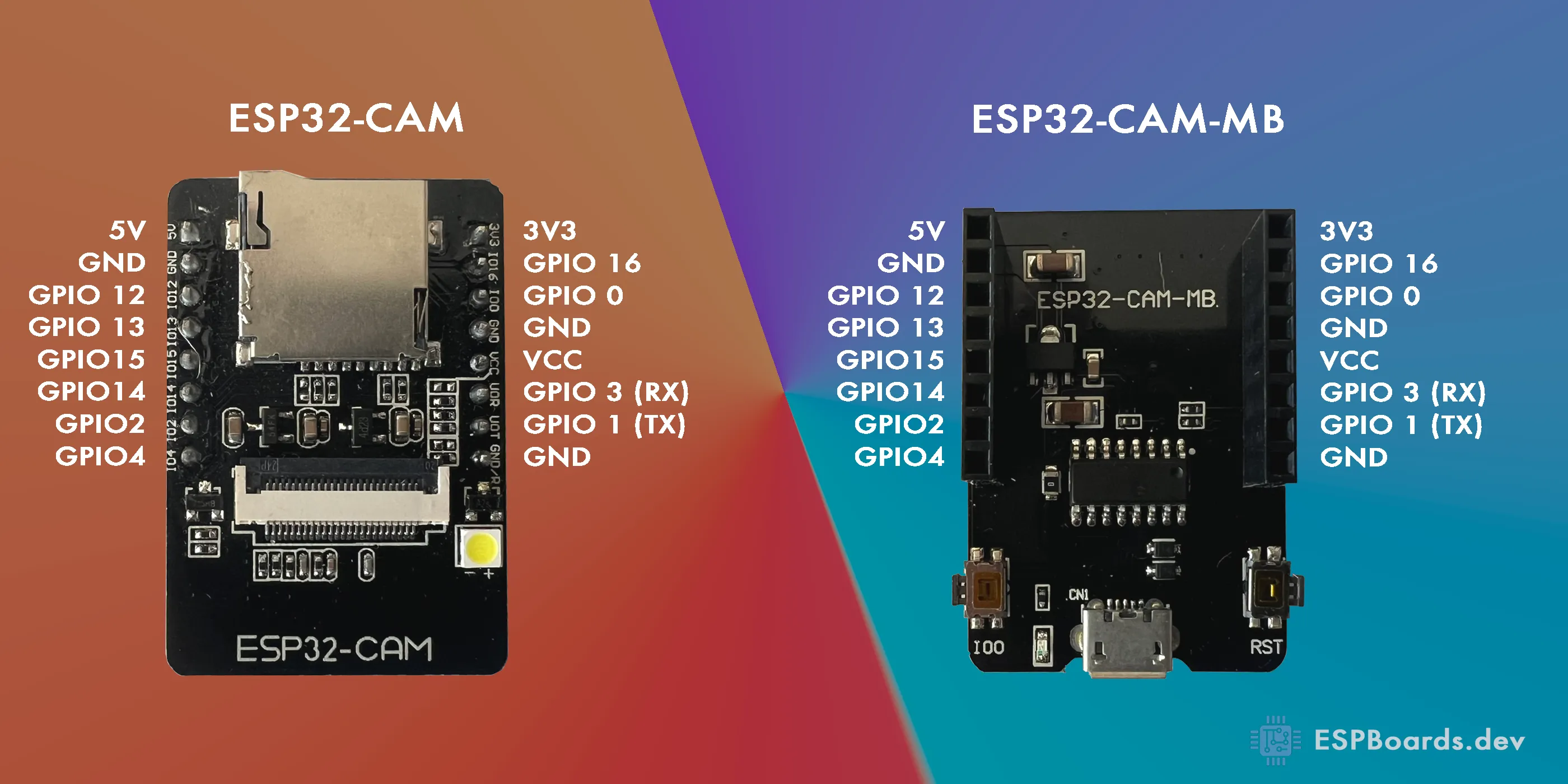
SD Card Pin Mapping on ESP32-CAM
The ESP32-CAM uses specific GPIO pins for interfacing with the SD card. These pins are shared with other peripherals, limiting their availability for general use. The SD card connections are as follows:
Key Notes:
GPIO4 is connected to the onboard flash LED, which may cause it to flash during SD card operations.
GPIO12 must be LOW during boot to avoid issues with the ESP32's boot process.
SD Card Modes and Available GPIOs
The SD card can operate in two modes: 4-bit mode and 1-bit mode. Each mode affects the availability of GPIOs.
4-Bit Mode
In 4-bit mode, all six GPIOs (2, 4, 12, 13, 14, 15) are used for SD card communication. This leaves only GPIO16 available for other purposes.
1-Bit Mode
In 1-bit mode, the SD card uses fewer pins, freeing up GPIO12 and GPIO13 for other uses. The configuration for 1-bit mode is as follows:
#include "SD_MMC.h"void setup() {SD_MMC.begin("/sdcard", true); // Enable 1-bit mode}This mode reduces data transfer speed but provides additional GPIOs for peripherals.
Managing GPIO4 (Flash LED)
To prevent the flash LED from interfering with SD card operations, you can initialize it manually:
Caution: Avoid keeping the flash LED on for extended periods, as it lacks a current-limiting resistor and may overheat.
Additional Tips for GPIO Management
GPIO16 is always available but may have limitations depending on your board's configuration.
If more GPIOs are needed, consider using an I2C GPIO expander like the MCP23017. This allows you to add multiple GPIOs while using only two pins (SDA and SCL).
Example of Using MCP23017
This approach can significantly expand the number of GPIOs available for your project.
Conclusion
The ESP32-CAM's GPIOs are heavily utilized by the camera and SD card. By switching to 1-bit mode, you can free up GPIO12 and GPIO13 for additional functionality. For more extensive GPIO requirements, consider using an I2C GPIO expander. These strategies allow you to maximize the ESP32-CAM's capabilities while maintaining SD card functionality.
SD gpio pins usage:-
https://stackoverflow.com/questions/73178340/esp32-cam-sd-and-camera-use-up-all-the-pins
more precise desc about sd 1 bit mode:
https://dr-mntn.net/2021/02/using-the-sd-card-in-1-bit-mode-on-the-esp32-cam-from-ai-thinker
https://github.com/alanesq/esp32cam-demo.
GPIO2 pin is used as a bootstrapping pin, and should be low to enter UART download mode. One way to do this is to connect GPIO0 and GPIO2 using a jumper, and then the auto-reset circuit on most development boards will pull GPIO2 low along with GPIO0, when entering download mode.
- Some boards have pulldown and/or LED on GPIO2. LED is usually ok, but pulldown will interfere with D0 signals and must be removed. Check the schematic of your development board for anything connected to GPIO2.
spi flash

SPI Pins
The ESP32-CAM features only one SPI (VSPI) in slave and master modes. It also supports the general-purpose SPI features listed below:
- 4 timing modes of the SPI format transfer
- Up to 80 MHz and the divided clocks of 80 MHz
- Up to 64-Byte FIFO
https://microcontrollerslab.com/esp32-cam-ai-thinker-pinout-gpio-pins-features-how-to-program/#google_vignette. several articles about the camera
https://gitmemories.com/index.php/jameszah/ESP32-CAM-RocketCam
hx-esp32-cam-fpv. spectacular air video
https://github.com/rolly46/hx-esp32-cam-fpv
ftp server
https://github.com/mtnbkr88/ESP32_FTPServer. for esp32 cam
https://github.com/nopnop2002/esp-idf-ftpServer
https://github.com/espressif/esp-idf. building environment and development software. python based
installation procedures:-
mkdir esp, cd esp,
git clone https://github.com/espressif/esp-idf
cd esp-idf
git submodule update --init --recursive
./install.sh
./export.sh
idf.py build or
idf.py main.py or
idf.py menuconfig
upload flash
idf.py -p /dev/ttyUSB0 -b 115200 flash
instructions to run build availabel
https://www.xda-developers.com/how-use-ftp-mac/. ftp replaced with smb or sftp
SD CARD
https://github.com/s60sc/ESP32-CAM_MJPEG2SD. pretty new project
https://forum.arduino.cc/t/esp32s-can-t-detect-mount-microsd-card-fix/914266. FIX
https://github.com/espressif/arduino-esp32/issues/4680
// Libraries for SD card
#include "FS.h"
#include <SD.h>
//#include "mySD.h"
#include <SPI.h>
// Define CS pin for the SD card module
#define SD_MISO 2
#define SD_MOSI 15
#define SD_SCLK 14
#define SD_CS 13
SPIClass sdSPI(VSPI);
String dataMessage;
void setup() {
// Start serial communication for debugging purposes
Serial.begin(115200);
// Initialize SD card
//SD.begin(SD_CS);
sdSPI.begin(SD_SCLK, SD_MISO, SD_MOSI, SD_CS);
if(!SD.begin(SD_CS, sdSPI)) {
Serial.println("Card Mount Failed");
return;
}
Serial.println("1");
uint8_t cardType = SD.cardType();
if(cardType == CARD_NONE) {
Serial.println("No SD card attached");
return;
}
Serial.println("Initializing SD card...");
if (!SD.begin(SD_CS)) {
Serial.println("ERROR - SD card initialization failed!");
return; // init failed
}
Serial.println("2");
// If the data.txt file doesn't exist
// Create a file on the SD card and write the data labels
File file = SD.open("/data1.txt");
if(!file) {
Serial.println("File doens't exist");
Serial.println("Creating file...");
writeFile(SD, "/data1.txt", "Reading ID, Date, Hour, Temperature \r\n");
}
else {
Serial.println("File already exists");
}
file.close();
logSDCard();
}
void loop() {
// The ESP32 will be in deep sleep
// it never reaches the loop()
}
// Write the sensor readings on the SD card
void logSDCard() {
//dataMessage = String(readingID) + "," + String(dayStamp) + "," + String(timeStamp) + "," +
// String(temperature) + "\r\n";
dataMessage = "Hello World \n";
Serial.print("Save data: ");
Serial.println(dataMessage);
appendFile(SD, "/data1.txt", dataMessage.c_str());
}
// Write to the SD card (DON'T MODIFY THIS FUNCTION)
void writeFile(fs::FS &fs, const char * path, const char * message) {
Serial.printf("Writing file: %s\n", path);
File file = fs.open(path, FILE_WRITE);
if(!file) {
Serial.println("Failed to open file for writing");
return;
}
if(file.print(message)) {
Serial.println("File written");
} else {
Serial.println("Write failed");
}
file.close();
}
// Append data to the SD card (DON'T MODIFY THIS FUNCTION)
void appendFile(fs::FS &fs, const char * path, const char * message) {
Serial.printf("Appending to file: %s\n", path);
File file = fs.open(path, FILE_APPEND);
if(!file) {
Serial.println("Failed to open file for appending");
return;
}
if(file.print(message)) {
Serial.println("Message appended");
} else {
Serial.println("Append failed");
}
file.close();
}
https://randomnerdtutorials.com/esp32-spi-communication-arduino/. esp32 cam spi pinouts
| SPI | MOSI | MISO | SCLK | CS |
| VSPI | GPIO 23 | GPIO 19 | GPIO 18 | GPIO 5 |
| HSPI | GPIO 13 | GPIO 12 | GPIO 14 | GPIO 15 |
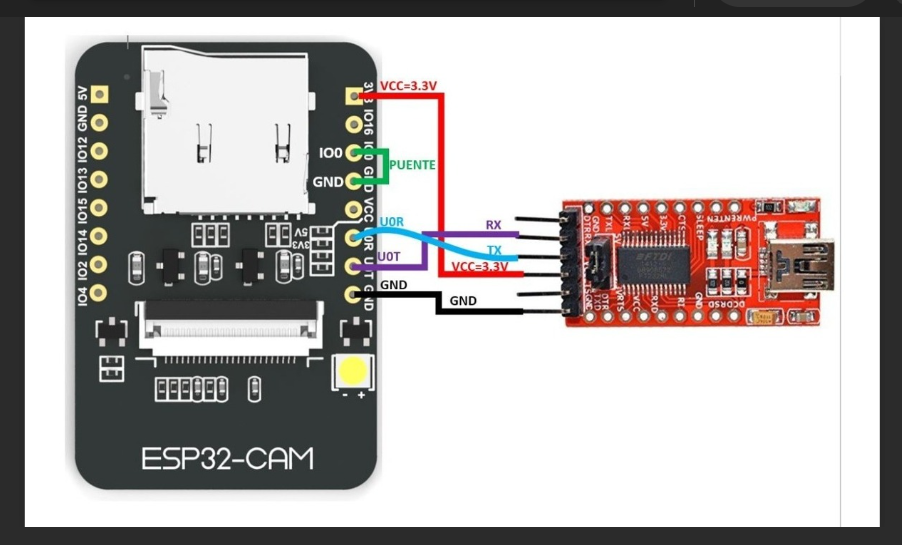
- https://community.home-assistant.io/t/esp-32-cam-flashing-upload-code-with-just-an-esp-01-usb-adapter/264945 flashing with esp01 programmer
- https://www.instructables.com/Fidi-ESP826632-Wiring/. how to connect usb serialhttps://www.makerguides.com/programming-the-esp32-wrover-cam/. some gd diagrams
- https://github.com/save2love/mi-ble-mqtt. Xiaomi sqttt gateway
- https://github.com/turlvo/KuKuMi. KuKuMi a webserver probing Xiaomi
- https://esphome.github.io/esp-web-tools/. web flash tools chrome and edge only
- https://github.com/TheWhiteWolf1985/ESPHomeGuiEasy/. Dashboard GUI
- ESP32/ESP8266 Web Server with Input Data on HTML Forms (microcontrollerslab.com)
- ESP32 Camera In Home Assistant - Gadget-Freakz.com
- ESP32 Camera Component — ESPHome
- Send Real-Time Sensor Data to Google Firebase with ESP8266 (how2electronics.com)
- Getting Started with Thonny MicroPython (Python) IDE for ESP32 and ESP8266 | Random Nerd Tutorials
- MicroPython Program ESP32/ESP8266 VS Code and Pymakr | Random Nerd Tutorials
- RootShell-coder/ESP01-Smart-Relay: Smart relay controller based on ESP8266 (ESP-01S) with web interface
- Connecting ESP-01 to the Relay Module V4.0
- ElToberino/Tobers_Timeswitch: Tobers Timeswitch is a versatile time switch for ESP8266 and ESP8266 based devives. Besides the classic timeswitch functions with optional twilight modes, it offers a countdown timer and a Master/Client mode that enables programming multiple timeswitches from a single device. Tobers Timeswitch is widely and easily configurable via web interface.
- ghassanirfan/timer_esp8266_schedule: This program is a smart timer system based on ESP8266 with a web interface. Users can set a schedule to control the relay through the web page. The schedule data is stored in LittleFS so that it remains stored even if the device is restarted.
- DrAlgoStrange/NodeMCU-Scheduled-Timer-Controller: A web-based timer controller system built on NodeMCU (ESP8266) that provides automated scheduling for up to 3 digital pins with real-time monitoring and configuration through a responsive web interface.
- sylvain-lp/ESP8266_Web_Timer: ESP8266 Web Server - Providing a Timer with Stop/Start button Web Page, and Stop button on ESP Board
- niksonii14/Timer-Control-Relay-device-using-ESP8266
- mjkloeckner/esp8266-remote-timer: ESP8266 based timer w/ remote control and NTP sync
- ryanamaral/alarm-scheduler-esp8266: ESP8266 ⏳Schedule alarms to occur at specific times via WebUI
- https://github.com/JohnHalfords/Timer-Clock-program-for-the-ESP8266
- https://github.com/DrAlgoStrange/NodeMCU-Scheduled-Timer-Controller. -- works
- https://github.com/desiFish/Smart-Aquarium-V3.1?tab=readme-ov-file -- pretty robust
- https://github.com/sugik0/esp8266-smart-relay-scheduler- 8 ch relays
- https://github.com/ryanamaral/alarm-scheduler-esp8266 - web socket time not synced
- https://github.com/G6EJD/ESP-SMART-Thermostat
- https://github.com/jim11662418/ESP8266_WiFi_Analog_Clock
- https://github.com/martin-ger/esp_wifi_repeater
- https://github.com/sparkfun/ESP8266_WiFi_IR_Blaster
- xreef/WebSocket-Esp8266-ESP32-Tutorial: Here the code of the tutorial with esp32 and esp8266 about Web-socket management -- websocket tutorials
- DrA1ex/esp_relay: Smart Relay Control for ESP32/ESP8266
- stanleyondrus/GrowLight_ESP8266: Grow light with websocket interface, manual control, and 24-hour scheduler, based on ESP8266 controlled 4-channel relay.
- arkhipenko/TaskScheduler: Cooperative multitasking for Arduino, ESPx, STM32, nRF and other microcontrollers super accurate timer
- xreef/WebSocket-Esp8266-ESP32-Tutorial: Here the code of the tutorial with esp32 and esp8266 about Web-socket management
沒有留言:
發佈留言