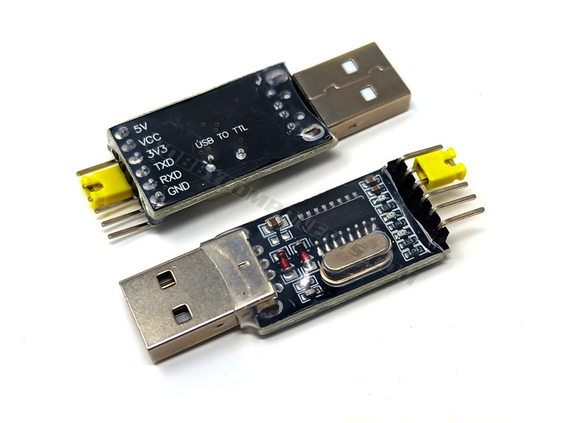
A CH340 based USB to serial TTL adapter. This module makes use of the common CH340 USB interface IC to provide a low cost alternative to the FTDI adapter. It also has the additional feature of being able to select 3.3V*/5V TTL levels by linking the VCC pin to either the 3.3V pin or 5V pin using the supplied jumper.
Note: This module is not suitable for use with ESP modules. Please see alternative item HCMODU0076 instead.
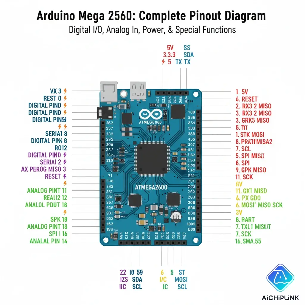
Pinnout:
1….5V (USB)
2….VCC (Input, connect to 5V or 3V3 pin via jumper)
3….3V3 (*measured at 3.67V)
4….TXD
5….RXD
6….GND


one at pa4~7 , one at b3~5,14
SPI is a full-duplex, bi-directional bus where data is both sent to the slave and received from the slave at the same time. Your SPI controller doesn't know if a given byte is glong from the master, or from the slave, or both. Therefore, whenever you send a byte, you must also read a byte, if only to throw it away. By the same token, you cannot receive a byte without sending a byte, even if the slave will throw it away.
Take a look at Wikipedia.
So, what you code is doing is
- Sending Read_ID to the slave.
- Reading and throwing away the byte simultaneously read out of the slave.
- Write 0 to the slave to enable the slave to send a byte of data.
- Read the data byte that was simultaneously read out of the slave.
- Loop back to #3.
By the way, such questions would be better suited for the EE Stack Exchange as it is more about the hardware protocol as opposed to programming.
a description on how to read write flash memory on esp32
esp32-flash-memory-spi-flash-arduino
https://stackoverflow.com/questions/36206794/spi-data-write-read
certain examples writing and reading from to spi flash in c
https://github.com/Xilinx/embeddedsw/tree/master/XilinxProcessorIPLib/drivers/spi/examples
sd card fatfs is much easier. though in stm32 mx platform
https://deepbluembedded.com/stm32-sd-card-spi-fatfs-tutorial-examples/
esp-idf forum has a pretty complete recommendation to deal with FAT on flash
https://esp32.com/viewtopic.php?t=43906
https://forum.arduino.cc/t/fatfs-for-external-flash-memory/1335861. esp32 on arduino
https://learn.adafruit.com/adafruit-hallowing/using-spi-flash. use circuitpython to read write files
circuit python
https://circuitpython.org/downloads?q=stm32
https://github.com/ESP32-S3_SD_Card. esp32 sd card
doc on vfs deployment
https://docs.espressif.com/projects/esp-idf/en/stable/esp32/api-reference/storage/vfs.html
transfer files over serial
https://stackoverflow.com/questions/4178168/how-to-programmatically-move-copy-and-delete-files-and-directories-on-sd. some good example codes
https://forum.arduino.cc/t/functions-to-wrap-fatfs-on-arduino/272413/18 sdfat vs fatfs
- Serial1 prints to hardware USART 1*
- Serial2 prints to hardware USART 2*
I also added these lines to setup to initialize SPI0 and SPI1 on pins I need
void setup(void) {
  SPI.setRX(0);  // (RP2040 ZERO pin 0, 4)
  SPI.setCS(1);  // (RP2040 ZERO pin 1, 5, 17)
  SPI.setSCK(2); // (RP2040 ZERO pin 2, 6, 18)
  SPI.setTX(3);  // (RP2040 ZERO pin 3, 7, 19)
  SPI.begin();

  SPI1.setRX(12);  // (RP2040 ZERO pin 8, 12)
  SPI1.setCS(13);  // (RP2040 ZERO pin 9, 13)
  SPI1.setSCK(14); // (RP2040 ZERO pin 10, 14)
  SPI1.setTX(15);  // (RP2040 ZERO pin 11, 15)
  SPI1.begin();
}#include <STM32ADC.h>
const int adcPin = PA0; // ADC pin
const int bufferSize = 100; // Size of the DMA buffer
uint16_t adcBuffer[bufferSize]; // DMA buffer
STM32ADC myADC(ADC1);
void setup() {
Serial.begin(9600);
// Initialize the ADC pin
pinMode(adcPin, INPUT_ANALOG);
// Initialize the ADC
myADC.begin();
myADC.setSampleRate(ADC_SMPR_1_5); // Set the ADC sample rate
// Start ADC with DMA
myADC.startContinuous(adcPin, adcBuffer, bufferSize);
}
void loop() {
// Wait for DMA transfer to complete
if (myADC.isContinuousDMAComplete()) {
// Process the data in adcBuffer
for (int i = 0; i < bufferSize; i++) {
Serial.println(adcBuffer[i]);
}
// Restart the DMA transfer
myADC.restartContinuous();
}
}


- ADS1115 ADC 4channel 16bit ADC+PGA
- https://how2electronics.com/how-to-use-ads1115-16-bit-adc-module-with-arduino/
- Multi-functions Shield

- Frequency Counter


- ESPboy
- https://www.instructables.com/Arduino-IC-Tester/
- ENC28J60 and Arduino Ethernet Module Tutorial (naylampmechatronics.com)
- Arduino Digital Clock Without RTC Real Time Clock Module on Tinkercad : 4 Steps (with Pictures) - Instructables
- 74HC595 Digital LED Display Based on Arduino( Code Provided) : 5 Steps - Instructables
- Serial to Parallel Shifting-Out with a 74HC595 | Arduino Documentation | Arduino Documentation
- Arduino Webservers Ethernet ENC28J60 With Thermometer DS18B20, I2C LCD and Power Over Ethernet POE for ZABBIX IOT Data Logging - Instructables
- Arduino Webserver Controller Using Ethernet ENC28J60 and Arduino : 4 Steps - Instructables
- Control and Monitor Arduino Over the Web Using ENC28J60 | maniacbug (wordpress.com)
- Control LED using Arduino & ENC28J60 Ethernet Module (how2electronics.com)
- Battery Level Monitor Using an Arduino | Arduino | Maker Pro
- Arduino and ENC28J60 Ethernet Controller, (320x480) TFT LCD, DHT22 Temperature / Humidity Web Server : 4 Steps - Instructables
- njh/EtherCard: EtherCard is an IPv4 driver for the ENC28J60 chip, compatible with Arduino IDE (github.com)
- EthernetWebServer_STM32 - Arduino Reference
- khoih-prog/EthernetWebServer_STM32: This is simple yet complete WebServer library for STM32 boards running built-in Ethernet LAN8742A (Nucleo-144, Discovery), ENC28J60 or W5x00 Ethernet shields. The functions are similar and compatible to ESP8266/ESP32 WebServer libraries to make life much easier to port sketches from ESP8266/ESP32. Ethernet_Generic library is used as default for W5x00. Now W5x00 can use any custom hardware / software SPI (github.com)
- Smart Home Automation Using Raspberry Pi and Arduino via Web - Hackster.io
- Interfacing DS18B20 1-Wire Digital Temperature Sensor with Arduino (lastminuteengineers.com)
- Irrigation Controller | MySensors - Create your own Connected Home Experience
沒有留言:
發佈留言